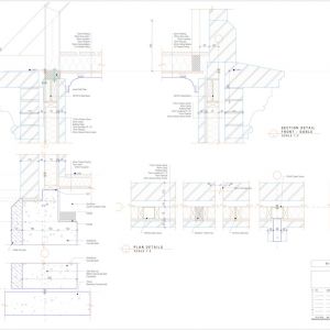
53 Preliminary CAD drawings
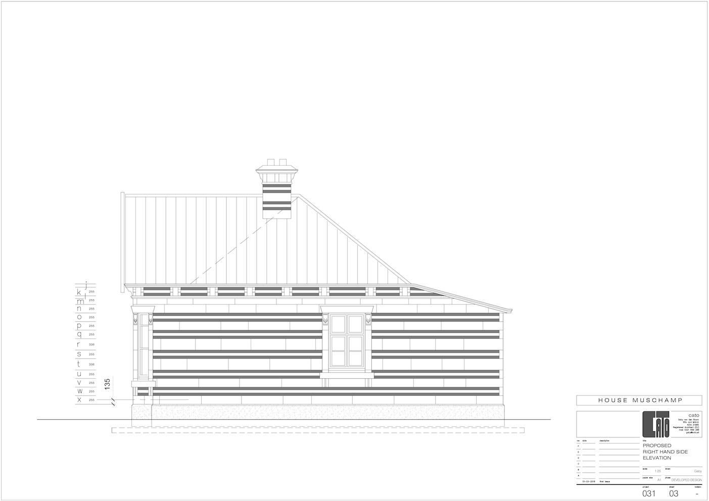
Based on measurements, sketches and photos from site, I have drawn the original house in plan, elevation, section and detail.
CAD requires to be exact while several measurements on site never are. However, after some interpoleren, I think I came pretty close.
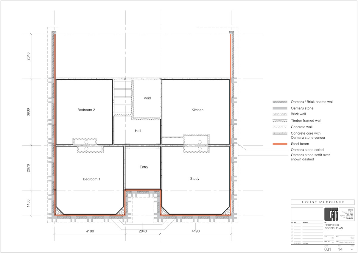
A copy of the drawings from the original house was the starting point for the set of proposed drawings.
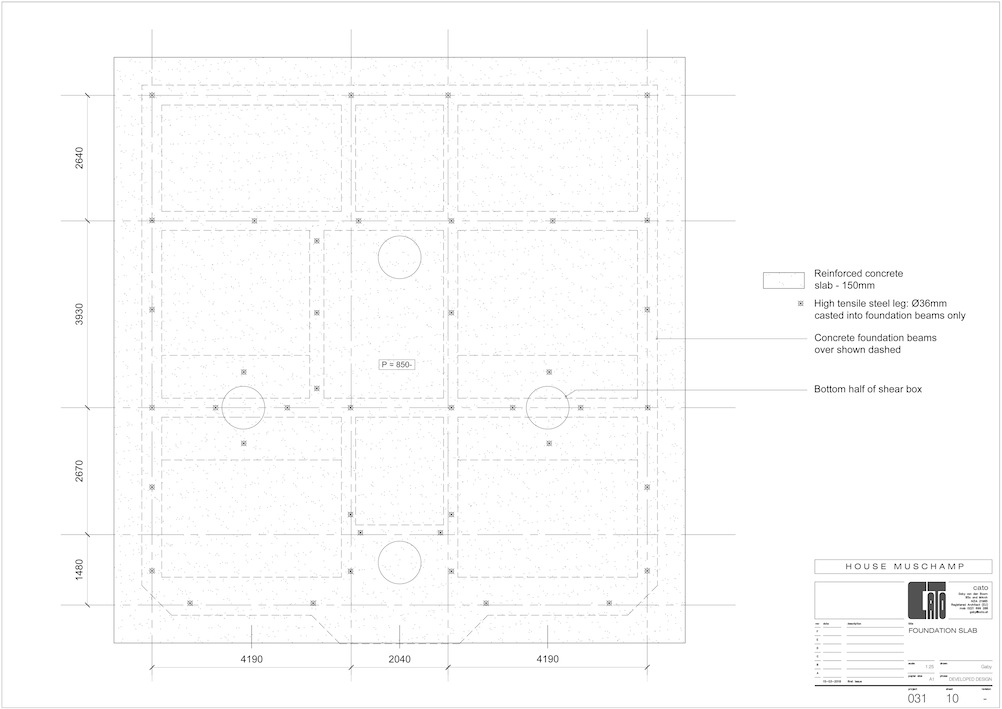
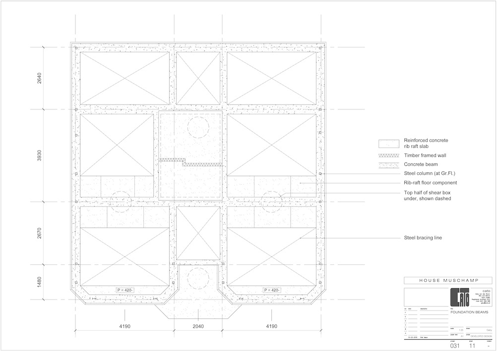
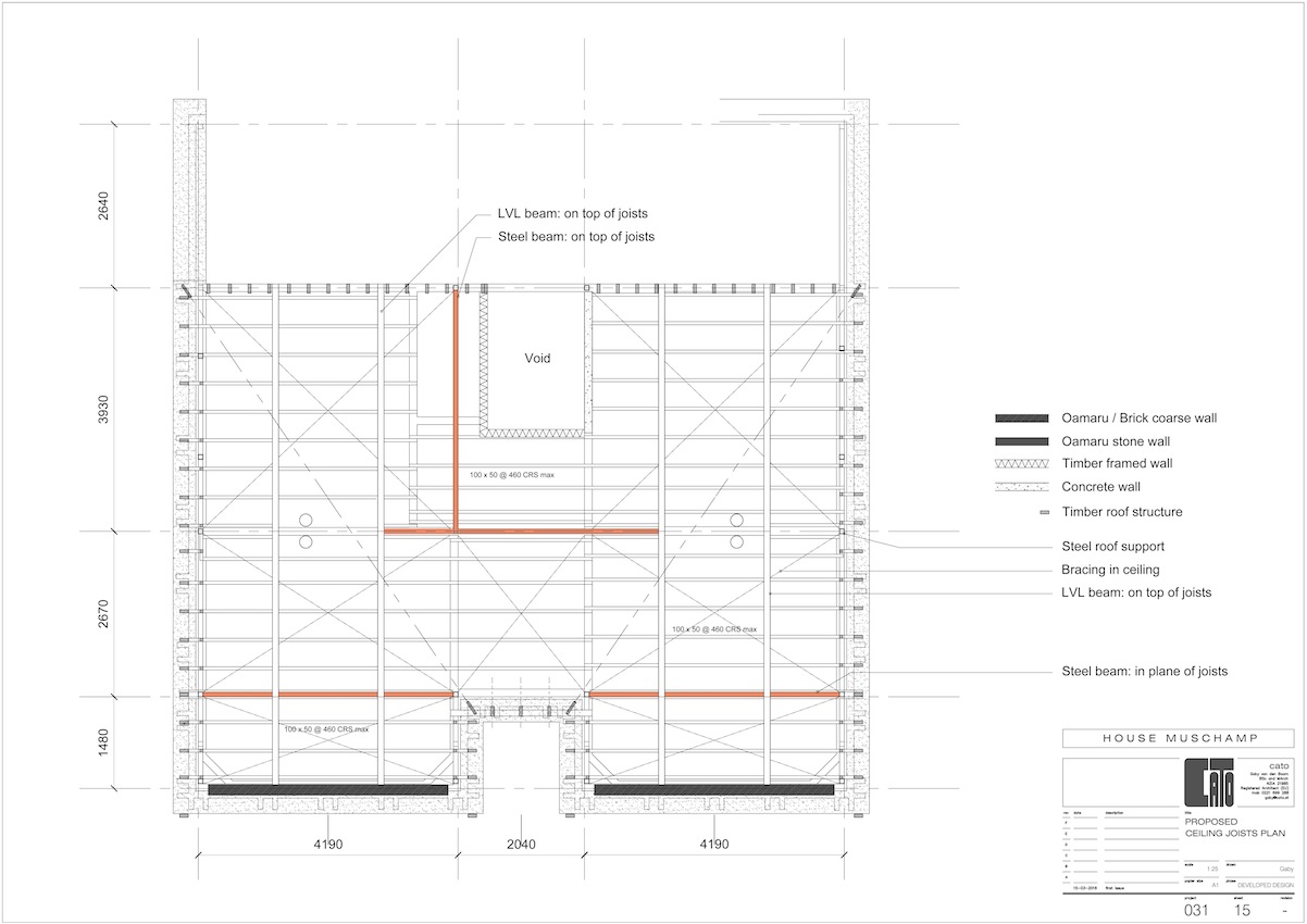
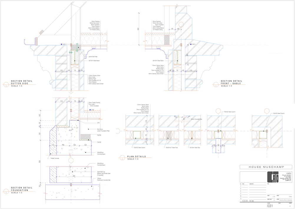
The plan of the house is amended as per earlier suggestions (refer to paragraph ..) and the structure of the internal walls is upgraded to (1) steel frame / timber infill / Omaru stone veneer for the peremeter wall and (2) a concrete core in between Oamaru stone for all interior walls.
The steel faming in the roof structure is mainly to provide bracing to the roof and the chimneys.
The steel framing in the walls is load bearing and (partly) for bracing.
The foundation is "disconnected between footing and beams to allow for movement between both components (base isolation)
The back of the house is still "open". The shape of the Living room will be inspired by the future location.
The CAD drawings reflect a Preliminary Design to be upgarded to Developed Design once the structure is verified.


